Log Splitter Hydraulics and How It Works
BASIC PARTS OF A LOG SPLITTER
The Log Splitter Hydraulic Circuit
Most log splitters use a hydraulic cylinder (like these) to push a cut piece of log into a sharpened wedge, which splits it.
The cylinder is driven by hydraulic oil, under pressure, produced by a hydraulic pump. An engine, or electric motor, drives the pump shaft, and supplies the power for the system. The oil from the pump runs to a hydraulic valve, which provides control over the movement of the cylinder.
The oil source is a hydraulic reservoir (tank) which is connected directly to the inlet port of the pump. Most use AW32 viscosity (approx 10 wt.) hydraulic oil, which is of course an important part of any hydraulic system. There is a vented filler cap on the reservoir which allows air to “breathe” in and out. A simple air filter in it keeps dirt out.
There is, or should be, a filter in the return line from the outlet of the valve to the reservoir. (Suction strainers in the inlet line are not a substitute for a return filter and are not recommended.)
A hydraulic relief valve controls the maximum pressure which can be created by the pump, and is a safety valve. It is usually located within the housing of the directional control valve. It is rarely in the pump. Without a relief, most hydraulic pumps will build pressure until something breaks, like a hose, or the cylinder, or the pump itself.
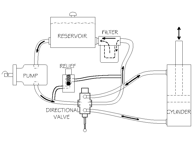
LOG SPLITTER HYDRAULIC CIRCUIT. The relief is usually incorporated within the directional valve.
THE HYDRAULIC PUMP
Most log splitters use a 2-stage gear pump which is a special type of hydraulic pump. They are rarely used in any other hydraulic systems. But they are widely available and relatively cheap because so many are sold for logsplitters.
Single Stage Pumps
Let’s start with the basics. Gear pumps are the most common, and least expensive type of hydraulic pump. They consist of 2 shafts, each with a gear which meshes with its twin to drive oil from the inlet port to the outlet or pressure port. Oil is trapped in the cavities between the gear teeth and carried around the outside of the gear toward the outlet port. The meshed gear teeth in the center keep oil from returning to the inlet side. One shaft sticks out of the housing and is driven by the engine. The other shaft is hidden within the pump housing. The one gear drives the other.
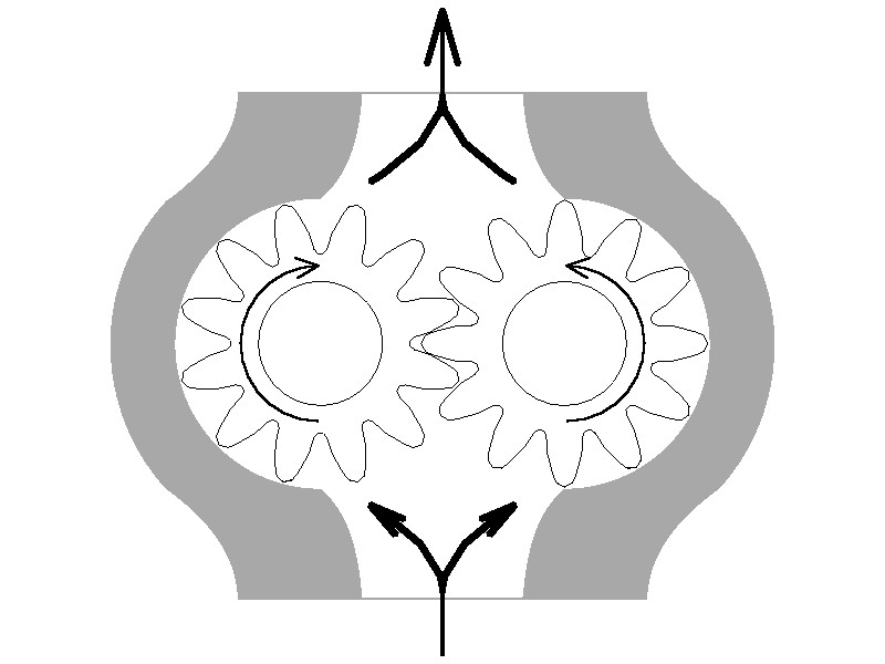
Single Stage Gear Pump
Two-Stage Pumps
Two stage pumps give splitters great performance using small engines. A 2-stage pump consists of 2 gear pumps in a single housing, and a bypass valve. One gear set is about 3 times the size (length) of the second. When the valve is in neutral & system pressure is low, both gear sets are pumping oil into the system. With a “16 GPM” pump, they will pump 16 GPM when the pump shaft is rotated (by the engine) at 3400 RPM. That is, the combination of the outputs from both gear sets equals 16 GPM.
When the valve is shifted it moves the cylinder quite quickly. But when the log hits the wedge, the resistance increases, and pressure is backed up against the pump. Now the bypass valve comes into play. When the back pressure reaches 700 – 800 PSI, oil from the larger set of gears is allowed to pass back to the inlet side of the pump (at almost 0 PSI) rather than being forced out the pressure port. So the only oil being forced out is from the small gear set. This takes a lot less horsepower and allows the use of a reasonably small engine to develop the high pressure necessary to split wood, while giving the cylinder good speed when not under a heavy load (which is most of the time). The opening and closing of the bypass is automatic, activated by the oil pressure. It’s so smooth it’s usually difficult to notice it is happening. So 2-stage pumps give our log splitters the best of both: high pressure when we need it, and high speed the rest of the time.
We sometimes see home made log splitters with single stage pumps, often reused from another type of machine. They are usually quite slow unless a much bigger than normal engine is used.
These pumps do not have a high pressure relief valve. You must provide it elsewhere in the system! Almost always within the directional valve.
THE HYDRAULIC CYLINDER
The cylinder is the “actuator” of the system: it converts the hydraulic pressure and flow into force to split the wood, and speed to make it efficient. The larger the cylinder diameter the more force (tonnage) it puts out, but the slower it will go: it takes more oil to fill, and so takes longer.
The most common size for log splitters is “4 x 24″, 4″ bore by 24″ stroke. With 2500 PSI from the pump it can exert over 31,000 lbs of push force. To compare, a 5″ bore cylinder can produce 49,000 lbs force with the same pump, over 1 1/2 times as much. But the 5” cylinder will go 36% slower, which is why they are not common on ordinary splitters.
Yes, I know, there are plenty of log splitters rated for much more force. And my 4 cylinder Toyota may be rated for 140 MPH. It’s a sales game. The big numbers are theoretical maximums, not practical working pressures.
The Hydraulic Log Splitter Valve
The hydraulic directional valve controls the motion of the cylinder. The “spool”, shifted by the handle, has 3 positions:
1. Pushed one way it shunts oil from the pump to the base port of the cylinder, causing it to extend. And it simultaneously allows oil from the rod-end port of the cylinder to flow into the return line.
2. When let go, the spool springs back to the neutral position; the oil from the pump is allowed straight through to the return port where it is recycled back to the tank, and the cylinder ports are blocked so the cylinder is stopped and held in position.
3. When the handle and spool are shifted the other way, the cylinder reverses direction, and again the oil from its opposite end port is allowed to return to the tank.
Most log splitter valves have 2 other features: an internal pressure relief valve , and a return detent.
The relief valve consists of a heavy spring with a compression adjustment screw, and a ball or poppet against a seat. This is in a channel between the pressure inlet port and the return port, with the ball or poppet blocking the flow. If the oil pressure reaches the adjustment setting, perhaps 2500 PSI, it overcomes the spring pressure, the poppet backs off, and oil from the pump is allowed to bypass directly to the valve outlet, thus limiting the maximum oil pressure in the system. At normal working pressures, the relief remains closed and is not involved in the circuit.
The return detent holds the spool in the cylinder return position so the operator can let go of the handle while the cylinder returns. But it is a detent with a special self-cancelling feature: when the cylinder “bottoms out”, the oil pressure increases suddenly automatically releasing the detent so the valve spool can spring back to neutral. That’s what’s different from a standard detent, which does not kick off by itself.
The Oil Reservoir or Tank
The hydraulic oil for the system is stored in a tank, usually steel. Reservoirs serve two important functions: They allow the oil to settle any air bubbles and contamination particles; and they allow the oil to cool while it’s not circulating.
To provide sufficient cooling, the tank should be sized to hold at least one minute’s worth of oil. (16 gallons for a 16 GPM pump.) Oil which is too hot, 180F, will harden seals, and will be too thin to lubricate the spinning pump parts, causing early pump failure. We recommend 150F as the working maximum oil temperature.
The reservoir has at least 3 ports:
1. A suction port, probably the largest, connected to the inlet of the pump.
2. A return port, often with a filter attached, connected to the valve outlet.
3. A filler port on top of the tank, with a breather cap attached.
The suction and return ports should be on the sides of the tank, a couple of inches above the bottom to avoid any sludge which may have settled there. The suction line should be low enough to never ingest any air, and the return should be low so as not to stir any air into the oil. Further, the 2 ports should be separated enough to avoid the hot returning oil from being immediately sucked back into the pump line.
Good reservoirs have a removable cover so the sludge can be cleaned out occasionally.
The Filter
Every good hydraulic system has a filter to remove fine contamination particles from the oil. The recommended rating is 10 microns, (10 microns equals 0.00039 inches; about 1/5 the diameter of a human hair). A filter this fine would plug the suction line, so it must be installed on the return, typically right at the tank return port.
The filter head has a pressure bypass built in (typically 15 PSI) so the filter won’t block the return if it’s dirty or the oil is cold. There may be a small gauge on the head to indicate when the filter element should be changed. If not, once a year is a rule of thumb.
Suction strainers in the tank are 100 micron or more, so can not catch the fine, damaging particles like the return filter. And if they get plugged they may starve the pump, greatly shortening its life. They are not recommended.
The Hydraulic Oil
Hydraulic oil is blended with chemical additives beneficial for hydraulic systems. They help resist wear, shed contamination, maintain viscosity when cold, resist foaming, rust and oxidation, etc. Typical viscosity is around SAE 10, usually labelled AW32.
Hydraulic oil is not subjected to the burning temperatures of combustion engines, so it usually lasts a long time. The recommendation is to change oil if it is excessively dirty, or milky (water contamination) or smells bad or burned. If not, it’s better to just change the filter and save the cost of an oil change.
Better quality oil decreases friction and heat. Cheap oil is not cheap!
TAKEAWAYS TO REMEMBER
- Hydraulic pressure (PSI) produces force,
- Hydraulic flow (GPM) produces speed.
- For all practical purposes they are independent of each other.
How to get more force? Either more pressure, or a larger cylinder. The pressure you probably can’t change much. Check the relief setting on your directional valve. It controls the maximum. We don’t suggest more than 2500 PSI, which is the practical maximum for most gear pumps. Yes they are sometimes rated at 3000 PSI or more. But that’s like driving your car 125 MPH. It may be able to do it, but all the time? Not such a good idea. Virtually all logsplitter pumps are rated for the same pressure. What’s the difference between pumps? Bigger gears, which produce more flow, which means more speed. And requires more horsepower to drive them. To get more force, you’ll need a larger bore cylinder. If you want the same speed as a smaller cylinder, you’ll need a larger pump, and probably a larger engine to drive it.
How to get more speed? Either more flow (GPM), or a smaller cylinder. The smaller cylinder won’t require more power, but will produce less force. More flow comes from a larger pump. So you’ll get the same force but will need to supply more horsepower to the new pump.
One other factor to consider for log splitter cylinders is the rod diameter. The larger the rod, the faster the cylinder will retract. (It takes less oil to fill the return end of the cylinder.) Of course it also increases the cost of the cylinder, but if you have the choice, choose the cylinder with the larger rod.
Have a Hydraulic Cylinder Project?
We’re here to help you! Give is a call or email today!